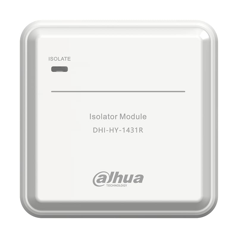
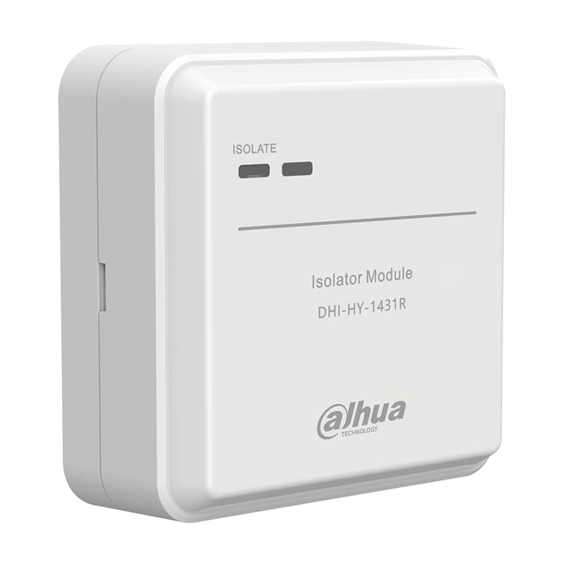
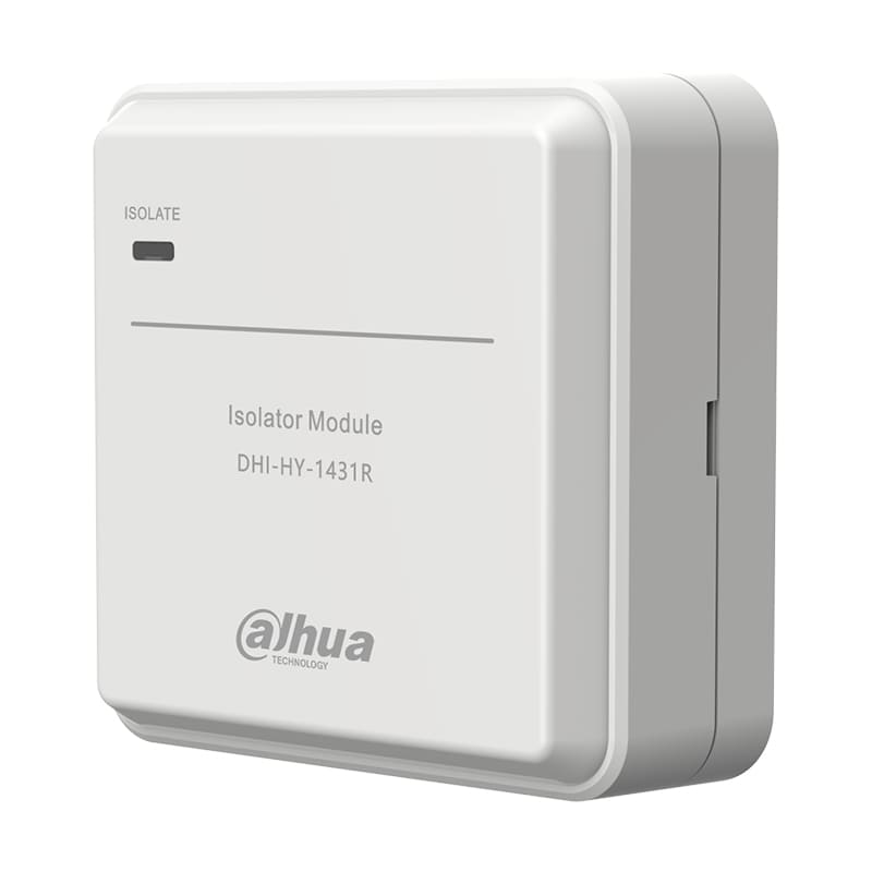
Description
Feature
- Compact Solution: With the assistance of a loop bus switch module and wiring, this system can transition from a radial to a loop circuit without replacing control panel
- Convenient wiring: Polarity-free with automatic identification
- Simple configuration: Shares the same configuration logic as theradial circuit without any special requirements
Technical Information
| Parameter | Introduction |
|---|---|
| Electrical | |
| Working Voltage | DC16V~ DC28V |
| Current |
|
| Indicator | Isolate: Yellow LED is constantly off when works normally and remains lit when short circuit occurs |
| Communication Wiring | |
| Wiring | Two-wire |
| Communication Distance | ≤ 1500 m |
| Environment | |
| Operating Temperature | –10℃ to +55℃ (+14℉ to +131℉) |
| Storage Temperature | –20℃ to +65℃ (–4℉ to +149℉) |
| Operating Humidity | ≤ 95% RH (no condensation) |
| Construction | |
| Color | White |
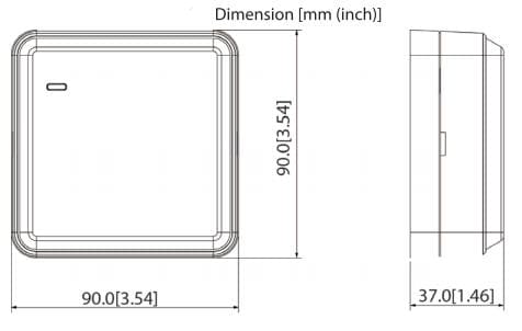
| Dimensions (with base) | 90 mm × 90 mm × 37 mm (3.54″ × 3.54″ × 1.46″) |
| Weight (with base) | 136.1g (0.3lb) |
FAQ
| Problem | Solutions |
|---|---|
| Output terminal is short-circuited, the isolate indicator does not light up |
|
Device Installation
1. Packing List
Check the quantity and model. If you find device damage or any loss,contact the after-sales service.
2. Installation Steps
Prerequisites
2.1 Disconnect the power supply of the device before installation.
2.2 The insulation resistance between buses should be greater than 20KΩ, and the insulation resistance of the bus to ground should be greater than 20MΩ.
2.3 Use RVS twisted pairs with a section area of 1.5 m㎡ or 1.0 m㎡ for the signal buses.
Test and Maintenance
1. Test
The isolate indicator is constantly off when works normally and remains lit when short circuit occurs.
2. Maintenance
To keep your device in good working condition, please follow these requirements.
2.1 Simulate alarm test: Test the device once half a year (recommended).
2.2 Before testing or maintaining, inform the proper authorities that the system is undergoing maintenance and will temporarily be put out of service. Disable the system to prevent unwanted alarms.