Description
Ⅰ.Overview
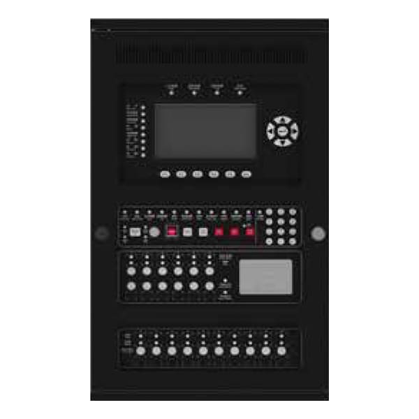
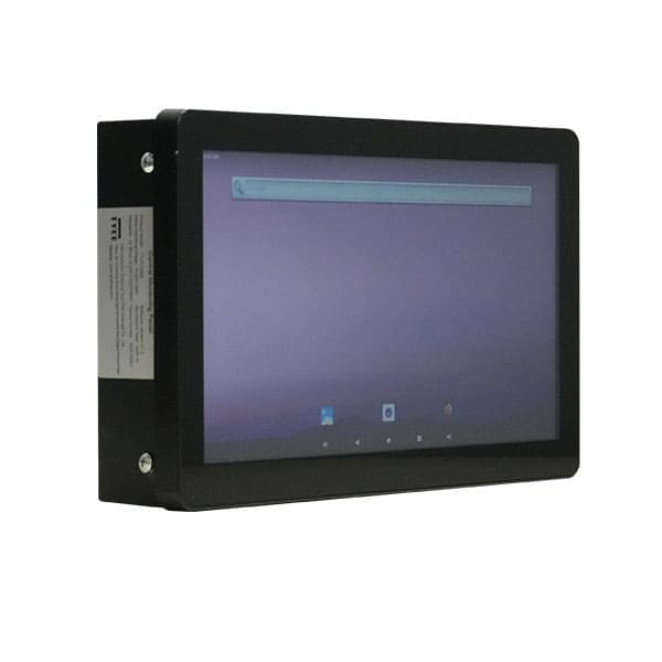
The TYI-P1000A is the central control unit for building emergency egress systems, specifically engineered for sudden emergencies such as fires and power failures. Through centralized management, intelligent linkage, and precise control of emergency lighting luminaires and egress marking signs, it provides reliable photometric environment guidance and system assurance for rapid and safe occupant evacuation. Its core value lies in transcending the passive activation mode of traditional emergency lighting, achieving “intelligent pre-judgment, active guidance, and full-process controllability.” This significantly enhances the scientific basis and safety of building emergency evacuation, making it an indispensable safety assurance device for modern high-rise buildings, large complexes, underground spaces, and other densely occupied locations.
Ⅱ.Luminaire Structure and Working Principle
1、Strong Regulatory Compliance: Strictly designed and manufactured in accordance with UL standards and UL Listed, ensuring compliance with US code requirements.
2、High Reliability: Industrial-grade industrial PC integrated design featuring a reliable and responsive capacitive touch screen.
3、Superior Anti-Interference Capability: Employs CAN communication. Emergency scenarios often present challenges such as fire-induced electromagnetic interference, line aging, and voltage fluctuations. CAN communication utilizes differential voltage signal transmission (voltage difference between CAN_H and CAN_L), effectively resisting electromagnetic interference and line attenuation. This ensures error-free transmission of control commands and status data even in heavy smoke and high-temperature environments, with a bit error rate below 10-8, significantly outperforming ordinary serial communication.
4、Power Redundancy Assurance: Seamless transfer between primary and backup power sources (transfer time ≤ 10ms). The backup power system features intelligent charge management to extend battery service life and ensure continuous power supply under emergency conditions.
Ⅲ.Core Features
1.Centralized Monitoring and Real-Time Status Detection: Enables unified management of all emergency lighting luminaires and egress marking signs within the network. It provides real-time data acquisition of device status (Normal, Fault, Emergency Active, etc.). A visual interface intuitively displays device distribution, operating parameters, and fault information, achieving “complete system visibility from a single screen.” The system can precisely locate the position and type of faulty equipment (e.g., lamp damage, line short circuit, low battery voltage), facilitating rapid maintenance.
2.Integrated Lithium Iron Phosphate Battery Backup: The controller incorporates a built-in Lithium Iron Phosphate (LiFePO4) battery pack. It automatically charges during normal mains power operation and seamlessly transfers to backup power immediately upon power failure, ensuring continuous operation of the controller and connected devices. The backup power provides a minimum duration of ≥ 90 minutes, ensuring stable power throughout the evacuation process.
3.Comprehensive Data Logging: Automatically records critical data, including system operation logs, emergency activation records, and fault history. The storage capacity is ≥ 10,000 records, with a data retention period of ≥1 year. It supports data export for traceability analysis, facilitating troubleshooting, system optimization, and compliance with fire safety inspections and routine regulatory requirements.
4.High Capacity Device Management: Each controller panel supports the management of up to 2040 luminaires.
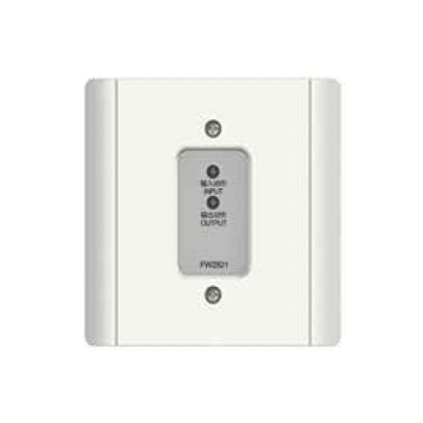
5.Expandable Communication Network: Supports connection with up to 8 communication bridge modules.
6.Fire Alarm System Integration: Provides dry contact interfaces for connection with the fire alarm system.
Ⅶ.Product Technical Features/Product Markings
| Specification Category |
Details | Specification Category |
Details |
|---|---|---|---|
| Rated Operating Voltage | AC100~277V | Battery Type | LiFePO₄ Lithium-ion Battery |
| Rated Operating Frequency | 50/60Hz | Battery Model | IFR21700-6000 |
| Input Power | 8W | Battery Specification | 3.2V, 6000mAh |
| Emergency Power | 5W | Battery Capacity | 6000mAh |
| Operating Environment | Damp Location | Charging Time | 24 hours |
| Ambient Temperature Range for Product Application |
0°C ~ 45°C | Minimum Initial Continuous Emergency Operating Time |
90 minutes |
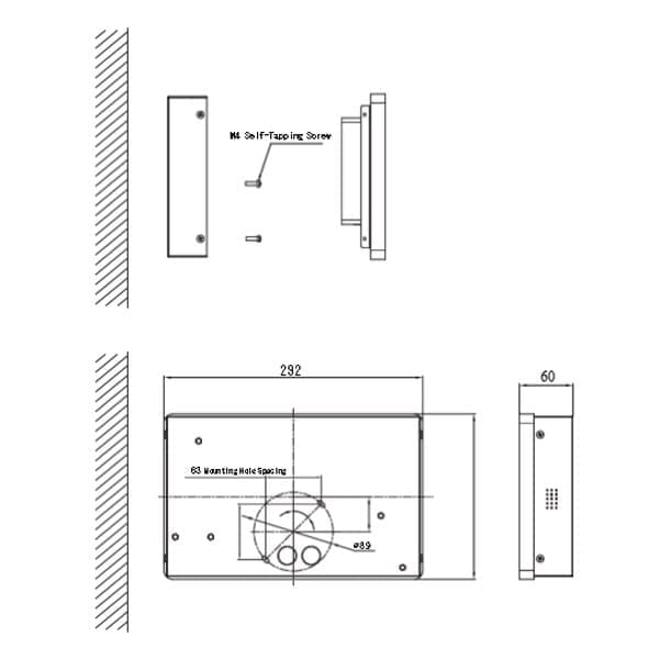
| Applicable Standard | UL 924 | Mounting Method | Wall Mounted |
1. Glossary
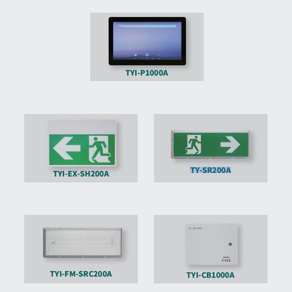
(1)Host: Emergency Lighting Controller, Controller
(2)Bridge: Central Power Supply, Power Supply
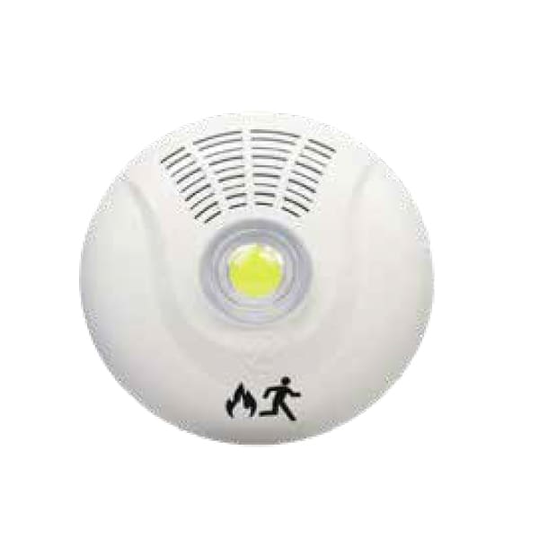
(3)Luminaire: Terminal
2. Interface Display
2.1 Interface Layout
(1)Top Status Bar: Application name, system time, software version number
(2)Middle Display Area: Displays functional interface
(3)Bottom Navigation Bar: Interface switching management (Home, Power, Terminal)
2.2 Home Management Interface
(1)Function Button Area: Login, Alarm Event, History Event, Mute, Chinese/English, Register, Emergency, Stop, Reset, Shutdown
(2)Controller Status Panel: Real-time display of all emergency lighting controllers’ working status
①Host number, status, type, backup voltage
②Power Overview: Total power supplies, emergency count, fault count
③Terminal Overview: Total terminals, emergency count, fault count
2.3 Power Management Interface
(1)Host Identification: Host number
(2)Power Overview: Total power supplies, emergency count, fault count
(3)Terminal Overview: Total terminals, emergency count, fault count
(4)Central Power Supply Status Panel: Real-time display of all central power supplies’ working status
①Central power supply box number, type, status, backup voltage
②Terminal Overview: Total terminals, emergency count, fault count
2.4 Terminal Management Interface
(1)Power Identification: Host number, central power supply number, central power supply version number
(2)Terminal Overview: Total terminals, emergency count, fault count
(3)Single Point Registration Switch
①Terminal number, rolling code, type
②Single Point Registration: Manually add terminal
③Single Point Deletion: Manually delete terminal
(4)Terminal Status Panel: Real-time display of all terminals’ working status
①Terminal number, type, status, rolling code
2.5 Emergency Lighting Controller Details Interface
(1)Basic Information: Host number, type, status, main power, backup power, charging, manual/automatic, backup voltage, version number
(2)Control Buttons: Emergency, Reset
2.6 Central Power Supply Details Interface
(1)Basic Information: Host number, central power supply number, type, status, manual/automatic, main power, backup power, charging, output circuit, monthly inspection, quarterly inspection, battery undervoltage status, output circuit open
status, version number, main power voltage, backup voltage, description
(2)Control Buttons: Light On, Light Off, Emergency, Reset
2.7 Terminal Details Interface
(1)Basic Information: Host number, central power supply number, terminal number, rolling code, type, status, main
power, backup power, description
(2)Control Buttons: Light On, Light Off
3. Button Functions
(1)Home: Jump to display home page information
(2)Power: Jump to display central power supply information
(3)Terminal: Jump to display terminal information
(4)Login: Obtain permission after login
(5)Alarm Event: Display stored alarm information
(6)History Event: Display stored historical information
(7)Mute: Cancel sound
(8)Chinese/English: Switch between Chinese and English
(9)Register: Register central power supplies and terminals
(10)Emergency: Control central power supplies and terminals for emergency
(11)Stop: Control central power supplies and terminals to stop emergency
(12)Reset: Control central power supplies and terminals to reset
(13)Shutdown: First cut off the main power of the emergency lighting controller, click Shutdown, and the system will shut down
(14)Single-click Controller: Display detailed information of the emergency lighting controller
(15)Long-press Controller: Jump to display all central power supply information registered by the selected emergency lighting controller
(16)Single-click Power: Display detailed power supply information
(17)Long-press Power: Jump to display all terminal information registered by the selected central power supply
(18)Single-click Terminal: Display detailed terminal information
(19)Light On: Control terminal to turn on
(20)Light Off: Control terminal to turn off
(21)Single Point Registration: Manually add terminal
(22)Single Point Deletion: Manually delete terminal