
Detection-to-Suppression Design
Commercial Fire Detection Systems: Linking Detection to the Right Suppression Response
A focused guide to coordinating fire detection, release logic and suppression using two practical examples: an electrically started aerosol extinguisher and an automatic tracking water cannon.
- Detection and suppression roles
- Release and feedback logic
- Two verified product examples
- Commercial procurement checklist

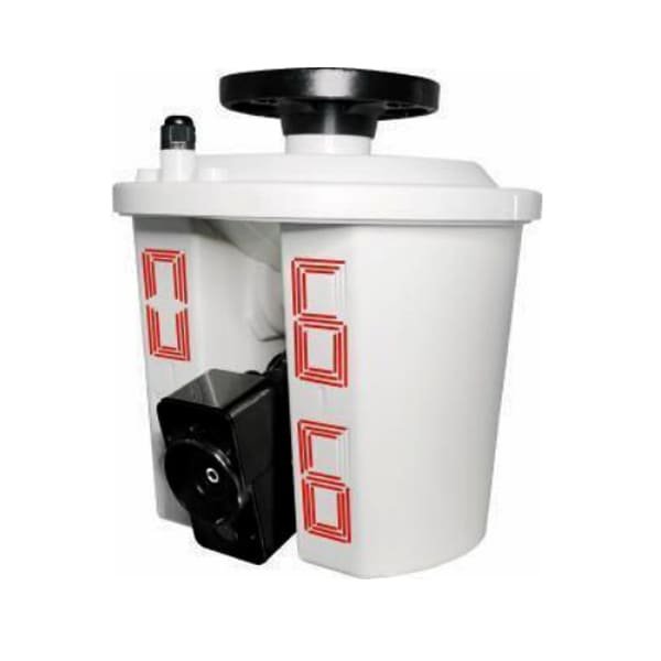
The most useful way to evaluate commercial fire detection systems is not to look at detectors in isolation. A commercial system must detect a fire condition, apply the correct control logic and initiate the response designed for that specific risk.
This distinction is especially important when the intended response is more than an alarm notification. Gas or aerosol suppression and automatic tracking water cannons are suppression technologies; they are not substitutes for the fire detection and control layer. Their safe operation depends on how detection, release, feedback and system supervision are engineered together.
1. What Commercial Fire Detection Systems Must Coordinate
A commercial fire protection sequence can be understood as four connected stages. The exact equipment and approval path depend on the building, hazard and applicable standard, but the functional relationship remains consistent.
- Detection Smoke, heat, flame or another approved input identifies a possible fire condition.
- Decision logic The control system evaluates zones, confirmation rules and programmed cause-and-effect.
- Release or actuation An approved output path starts the selected suppression response.
- Feedback and supervision Status signals confirm operation or indicate a fault requiring attention.
The key design question is therefore not simply “Which detector should be used?” It is “What verified sequence must occur from the first detection signal to the final suppression action?”
2. Example: Electrically Started Aerosol Suppression
QRR1G-U02-US Aerosol Fire Extinguisher
This product is relevant to commercial fire detection systems because the published starting method is electric and the unit provides a passive switching feedback signal. Those two details affect how the suppression device can be connected to an approved releasing and monitoring arrangement.
- Operating temperature: −40°C to +54°C
- Starting method: electric
- Discharge time: 11.1 seconds, ±5 seconds
- Feedback: passive switching signal
- Feedback contacts: normally open and normally closed
- Published protective space: 16.67 m³
- Published validity: 15 years
- Certification listed: UL/ULC 2775 Standard
Why the electric start matters
An electric start creates a defined interface between the suppression unit and the fire control or releasing arrangement. However, it does not by itself define the complete release sequence. The project designer must still determine the required detection inputs, confirmation logic, warning period, manual controls, isolation functions and supervision required by the applicable design standard.
Why feedback matters
The listed passive normally open and normally closed switching signal can support status monitoring within a compatible control design. Procurement documents should state exactly what the feedback represents and how it will be displayed, logged or used by the commercial fire alarm system.
3. Example: Automatic Tracking Water Cannon
ZDMS0.6/10S-LZⅡ Automatic Tracking Water Cannon
This model combines automatic tracking and positioning with a high-flow water discharge. It should be treated as a coordinated detection, control and hydraulic system rather than as a conventional point detector with a nozzle.
- Working voltage: DC 36 V
- Product size: 29.4 × 29.4 × 32.5 cm
- Flow rate: 10 L/s
- Published protection radius: 28 m
- Published positioning time: ≤30 seconds
- Travel range listed on the page: vertical 360°, horizontal 120°
- Certifications listed: HS250122, ICR and VC
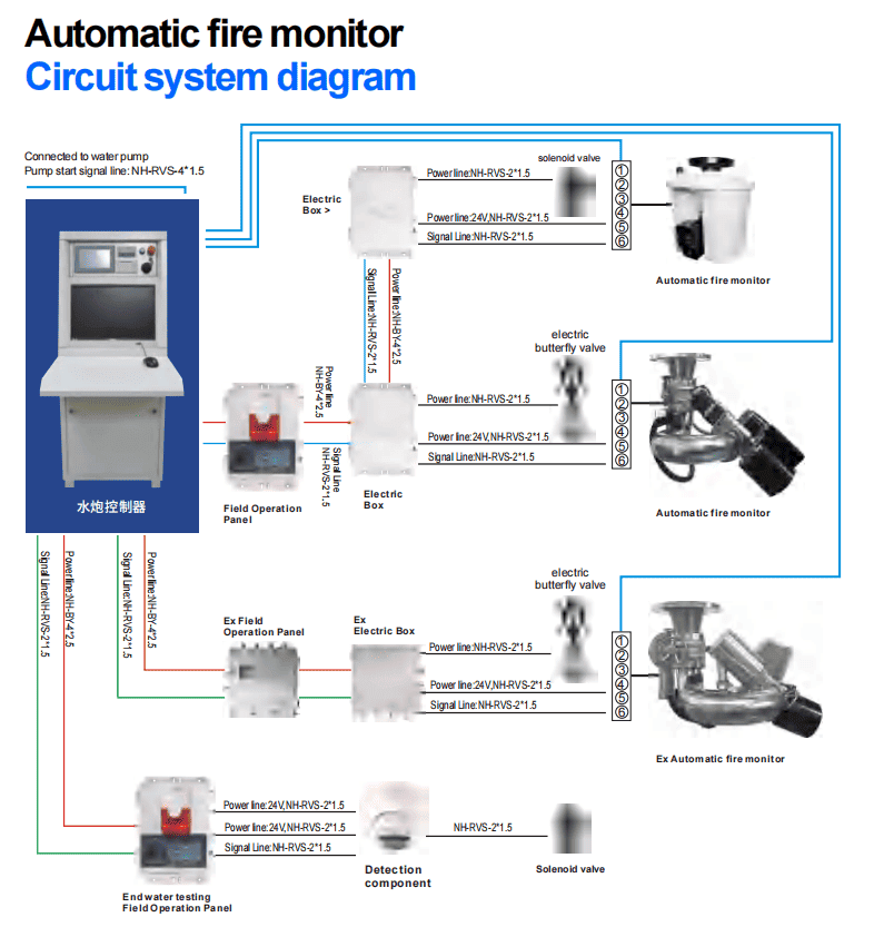
The product page also includes a circuit system diagram showing the automatic fire monitor connected with control equipment, valves, pump-start signaling and a detection component. This is useful because it demonstrates that the cannon is only one part of a larger system architecture.
4. How the Two Suppression Interfaces Differ
| Design question | Aerosol extinguisher | Automatic tracking water cannon |
|---|---|---|
| Main activation concept | Electric start from a compatible releasing arrangement | Automatic tracking and positioning coordinated with control and water-supply equipment |
| Published feedback or control information | Passive switching feedback, normally open and normally closed | Product page includes a system diagram with control, signal and pump interfaces |
| Published capacity indicator | Protective space: 16.67 m³ | Flow rate: 10 L/s; protection radius: 28 m |
| Key external dependency | Approved detection and release logic | Detection/positioning, valves, controls, pump and water supply |
| Critical procurement check | Confirm agent design, device quantity and release sequence | Confirm coverage, hydraulic design, movement axes and system interfaces |
5. Five Questions to Resolve Before Selecting Equipment
What exactly initiates suppression?
Define whether release follows one input, confirmed inputs, a dedicated detection subsystem or another approved cause-and-effect sequence.
How is unintended activation controlled?
Specify verification logic, manual controls, maintenance isolation and fault handling according to the project standard and risk assessment.
What feedback must reach the fire panel?
Identify release status, valve or pump status, faults, disabled conditions and any signals required for operator action.
Which system owns the final decision?
Clarify the boundary between the building fire alarm panel, dedicated releasing controls and the suppression equipment’s local controller.
What happens after activation?
Define alarm indication, event logging, shutdown interfaces, reset conditions and the inspection required before the system returns to service.
Are all interfaces documented?
Obtain terminal information, signal type, power requirements and approved cause-and-effect documentation before procurement.
6. Commercial Fire Detection Systems Procurement Checklist
- Protected room or area dimensions
- Fire hazard and expected fuel type
- Required detection technology
- Detection zoning and confirmation logic
- Fire alarm panel or releasing-panel details
- Suppression start signal type
- Required feedback and supervision points
- Power supply and standby-power requirements
- Water supply and pump data where applicable
- Environmental and operating-temperature limits
- Applicable certification and design standards
- Manual control and maintenance-isolation requirements
- Required system drawings and terminal diagrams
- Commissioning and acceptance-test responsibility
7. Frequently Asked Questions
Is a gas suppression unit itself a commercial fire detection system?
No. It is a suppression device. A complete commercial fire detection system includes the detection and control functions that determine when and how an approved suppression output is initiated.
Can a normal fire alarm output directly start suppression equipment?
That cannot be assumed. The release path, monitoring, confirmation logic and approval requirements must be defined by the applicable design standard and compatible equipment documentation.
Does the 28 m protection radius complete the water cannon layout?
No. It is one published product parameter. Final layout also requires confirmed movement coverage, mounting position, obstructions, hydraulic performance and approved system design.
Why is feedback important after suppression activation?
Feedback helps the control system and operators distinguish between a command being issued and equipment actually changing state. The exact feedback points must be defined for the selected equipment and project.
Build the Detection-to-Suppression Interface Before Ordering
Send FireMarket the protected area, hazard information, required detection method, fire alarm or releasing-panel details, suppression preference and applicable certification requirements. We can help compare supply options based on the documented project needs.
Contact FireMarketProduct parameters in this article are taken from the corresponding FireMarket product pages available at the time of preparation. Final specifications, compatibility, certifications and system design must be confirmed in the approved quotation, technical datasheet and project documentation before ordering.