Fire Alarm System Components: Main Components of an Addressable System

Table of Contents

Understanding the main fire alarm system components helps explain how an addressable fire alarm system works. This article covers the control panel, detectors, manual call points, input and output modules, loop wiring, and backup batteries.

Addressable Fire Alarm Control Panel (FACP)

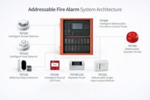
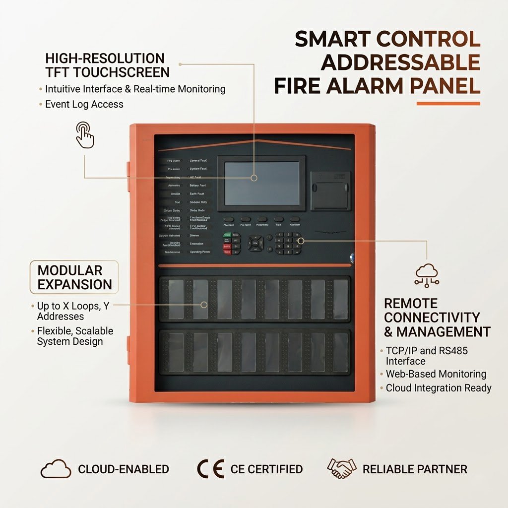
The FACP is the central unit of an addressable fire alarm system. It monitors connected devices, processes alarm signals, displays system status, and manages programmed responses. It is typically installed in a fire control room or designated equipment room.

The FACP receives signals from connected detectors and modules through the signaling loops. By identifying each device through its assigned address, it can display the source of an alarm or fault and provide operators with real-time system information. Depending on the system configuration, the panel can also activate notification devices and initiate other programmed control functions.

The TX7004 Intelligent Fire Alarm Control Panel supports up to 1,016 devices across four loops. It features 160 built-in LED zone indicators for fire and fault status, along with an LCD screen for displaying system and device information. The panel also includes a built-in printer and supports programming via PC or keypad.

Addressable Fire Detectors

Addressable fire detectors identify fire-related conditions and report alarms or faults to the FACP using a unique device address. Common types include smoke detectors, such as the TX7100 Intelligent Smoke Detector, which detects smoke particles and is effective for many smoldering fires; heat detectors, such as the TX7110 Intelligent Heat Detector, which responds to fixed temperature thresholds or rapid temperature rises; and multi-sensor detectors, such as the TX7120 Intelligent Multi-sensor Fire Detector, which combines optical smoke detection with rate-of-rise heat detection.

Addressable detectors communicate with the FACP through the system’s signaling loop. When a detector reports an alarm, fault, or other supported status, the panel processes the signal and displays the corresponding device information and event according to the system configuration.

Manual Call Points

Manual call points allow occupants to trigger a fire alarm when they discover a fire. Unlike automatic smoke and heat detectors, which detect smoke particles or temperature changes, manual call points rely on human action to initiate an alarm. In an addressable system, each call point has a unique address, allowing the FACP to identify which device has been activated.

Input and Output Modules

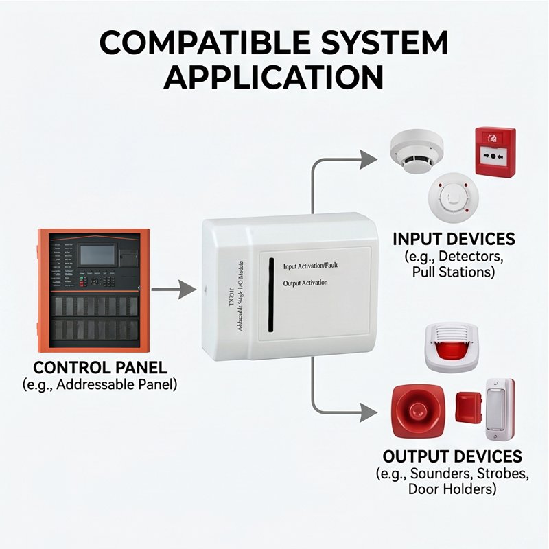
Input and output modules connect the FACP with compatible external devices. Input modules receive signals from connected equipment and transmit status information to the panel, while output modules receive control signals from the FACP to activate external devices. Each addressable module has a unique address, allowing the FACP to identify the relevant point and process signals according to the system configuration.

Loop Wiring and Communication

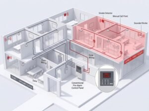
Loop wiring connects addressable field devices to the FACP, enabling communication for alarm, fault, and status information. In a typical loop arrangement, the cable leaves the FACP, connects the devices, and returns to the FACP, providing communication paths in both directions. If a cable break occurs, the panel can report the fault, while devices may remain operational through the intact path, depending on the system design.

Power Supply and Backup Batteries

The power supply provides the electrical power needed for the FACP and connected system devices during normal operation. If the main power supply fails, backup batteries provide power to keep the system operating according to its design requirements. The control panel also monitors power supply faults and battery conditions, alerting users to issues that may affect system reliability.

How These Components Work Together

When a smoke or heat detector detects conditions that meet its alarm criteria, or a person activates a manual call point, the device sends a signal to the FACP through the system’s compatible communication loop. Each addressable device has a unique address, allowing the panel to identify the source of the signal and display the corresponding alarm or fault information.

After processing the incoming signal, the control panel responds according to its programmed logic. It can activate connected sounders, strobes, or sounder strobes to warn building occupants. Where the system design requires additional actions, compatible input and output modules can monitor external equipment or trigger configured control functions. These operations depend on the connected devices, system programming, and interface compatibility.

Throughout operation, the control panel and associated monitoring functions help identify issues such as communication faults, power supply failures, or battery problems. The primary power supply supports normal operation, while backup batteries provide power during a mains interruption, subject to the system’s design and capacity.
Looking for a Fire Alarm Solution for Your Building

Explore FireMarket’s fire alarm products or contact our team to discuss your project requirements.

Frequently Asked Questions

How many detectors and devices can one system support?

The capacity of an addressable fire alarm system depends on the control panel and system configuration. The TX7004 Intelligent Fire Alarm Control Panel supports up to 254 devices per loop, with a total capacity of 1,016 devices across four loops. The actual number of detectors depends on the number and types of devices connected to the system.

Consider the building size, number of devices, required loop capacity, system functions, and potential future expansion. You should also check device compatibility and applicable project standards. For more accurate product recommendations, prepare your project requirements or bill of quantities (BOQ) for review.

Not always. Compatibility depends on the control panel’s communication protocol and supported devices. Before combining products from different manufacturers, check the manufacturer’s compatibility requirements to ensure the devices work correctly with the system and meet applicable project standards.

Related Posts